by Mike OBrien on 03/07/2012
YFS CA-60a VACUUM TUBE PREAMPLIFIER
Modern music sources supply output voltages in the 1.0 to 2.0 volt range as opposed to phono cartridges where output levels are millivolts (0.001) or microvolts (0.000001). It makes sense to design a preamplifier optimized specifically for these modern sources. Our main listening room is equipped with such a unit employing an interesting WWII era topology. The inspiration came from the classic text from the MIT Radiation Lab Series, "Vacuum Tube Amplifiers" by G. Valley and H. Wallman. This monumental work was completed in 1948 (1st Edition) and resulted in 28 volumes, one of which was volume 18 mentioned above. Each time we thumb through it we seem to find something we missed or previously misinterpreted. Although complete functioning circuits (other than high gain RF amplifiers) aren’t shown, application examples and suggestions are scattered throughout the text. I believe it is currently available in hard copy (4th printing of 1st edition) and there are some of the original texts still available on Amazon and other websites. Chapters 10 and 11 covering frequency selective amplifier design and direct-coupled amplifier design illustrate applications of cathode coupled and differential input stages.
In the late 1980’s when The Library was tossing old magazines and journals we ran across a 1957 article in a volume of the IRE Transactions on Audio. The article was titled “Some Augmented Cathode Follower Circuits” by J. Ross MacDonald, who worked for Texas Instruments during WWII. The first paragraph and a few highlights read as follows:
The circuits, which are discussed in this paper, have very high input impedance, low output impedance, wide dynamic range, extremely low distortion, response from zero to the megacycles/second range, and input-output transfer ratios very close to or exceeding unity with no phase reversal. They are suitable for many applications. They may be used as grid drivers of high-power output tubes and will supply 100ma or more of positive grid current in such service. They are suitable as isolation stages or buffers, particularly where their extremely high input impedance characteristics are desirable. Their lack of phase reversal together with transfer ratios equal to or greater than unity and their vanishingly small distortion as well as wide dynamic range makes them particularly useful in active electronic filters and frequency selective amplifiers.
The circuits to be discussed occupy a somewhat intermediate position between ordinary cathode followers and operational amplifiers.
The circuit, shown in Fig 1, is more complex than an ordinary cathode follower, has an output resistance of 5.6 ohms, an input-output transfer ratio of 0.986, and can supply up to 200 ma of positive drive current without excessive distortion.
WOW! Perfect. What more could you ask for (if it’s true) in a line amplifier requiring only 12 dB of gain? We proceeded to breadboard multiple versions of the circuits described in the paper. We even added a few twists with MOSFET or JFET transistors where appropriate. The original CA-60 was all tube with 280V positive and negative rails. It sounded great but was impractical (at the time) to commercialize. Today it would not be an issue considering what the average audiophile preamplifier currently costs! Many incarnations including permutations and combinations of solid state current sources, MOSFET driven plates, MOSFET outputs, and regulated supplies were built and tested.
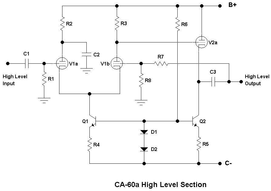
One of the final CA-60a topologies is shown below. It employs a 12AX7 as the input tube (V1a&b) and one-half of a 12AU7 (V2a) as the output buffer. Using all 12AU7 tubes is also possible at the expense of overall gain. Both sounded good but slightly different, so the 12AX7 won out since we have a good stock of low noise matched section NOS units (these were from select stock for an analog computer). As usual, one objective was to use common, relatively inexpensive tubes.
The input circuit looks like a standard differential input stage at first glance with C1 and R1 defining input impedance and low end roll-off. Plate voltages are matched by making R2=R3, however capacitor C2 bypasses the AC signal to ground forcing V1a to act as a cathode follower in AC terms. This feeds the second tube V1b via the cathode, leaving the grid as a feedback input. Several versions with separate regulators and driven plate via an integrator were tried but this simple arrangement was sonically equal. Output cathode follower V2a is DC coupled from the plate of V1b. Both the input and output stage have current sources made up of Q1-R4, and Q2-R5 to increase linearity. Diodes D1 and D2 along with bias resistor R6 form the voltage reference for the current sources. The feedback network composed of R7 and R8 defines the gain. Output capacitor C3 blocks DC from the cathode of V1b. It is possible to choose components to allow DC feedback directly from the cathode of V2a but that limits the choices of both open and closed loop gain. All capacitors are polypropylene or polystyrene while resistors in the amplifier circuit are either 1% metal film or 1% wire wound. Some carbon composition resistors were used in the power supply.
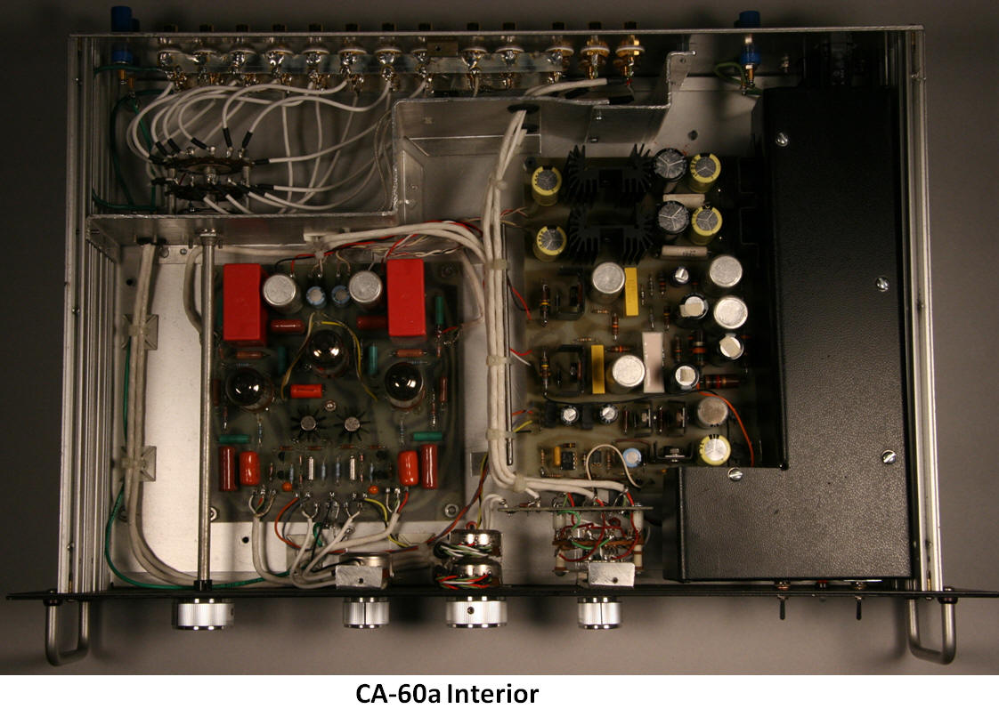
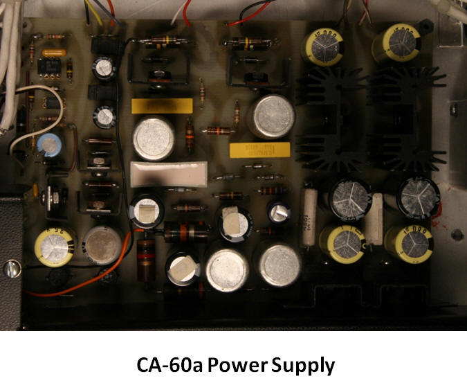
The power supply employs separate transformers for the filaments, B+, C-, and delay circuits. Individual high voltage regulators, negative regulators, and filament regulators are included. The delay operates an output shorting relay and controls the standby function. Transformers and AC portions of the supply are fully shielded.
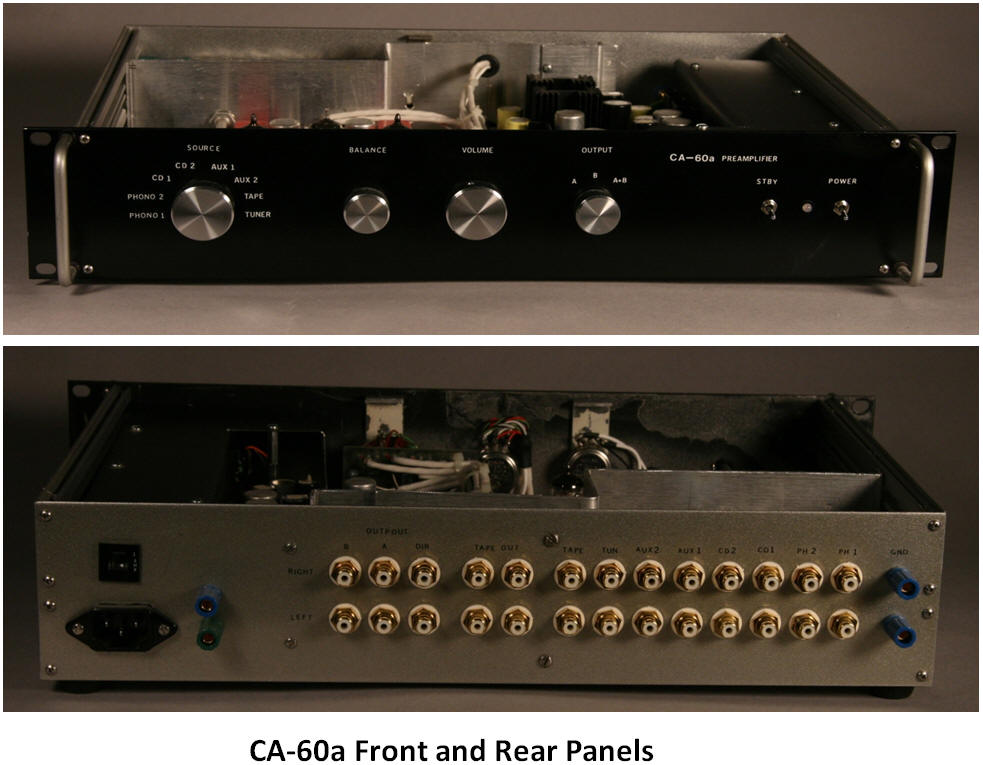
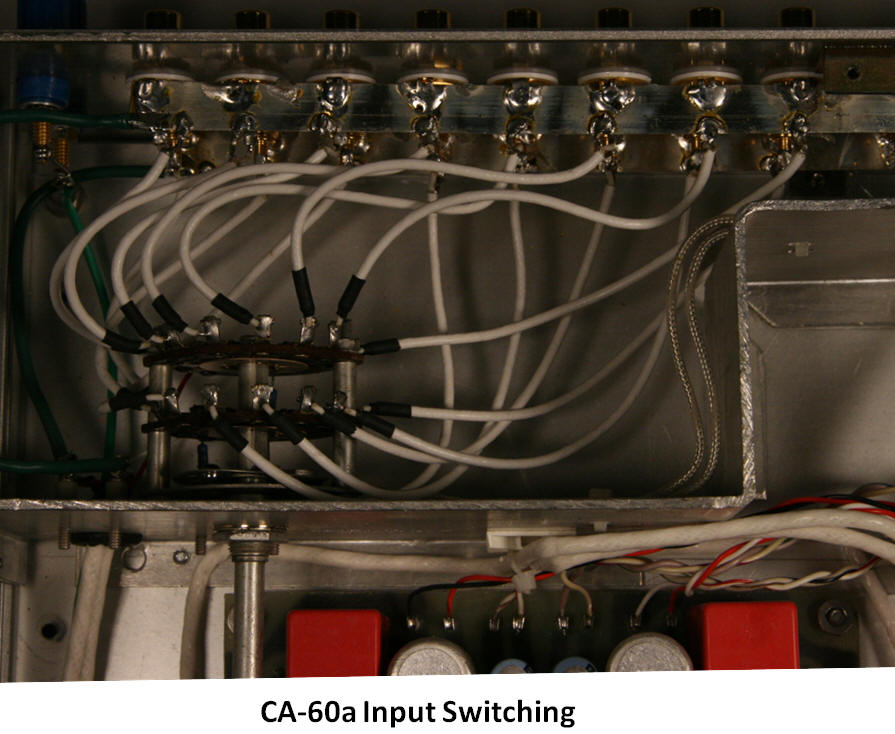
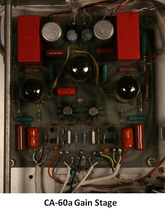
The CA-60a physical layout is shown in the photos below. This version includes eight high level inputs, two for phono stages, and six for normal inputs. Output switching allows the output signal to be routed to A, B, or both A & B outputs. A direct output is included after the volume and balance controls allowing it to function as a passive “preamp” if desired. This arrangement is very convenient for comparing sources, new preamp circuits, and power amplifiers. Internal shielding of the input and power supply sections reduces noise and cross talk. All power and signal wire is PTFE insulated stranded silver plated copper.
Frequency and phase response from a PSPICE model is shown. The theoretical response shows a bandwidth from 0.10 Hz to 300 kHz with a phase shift of only +/- 2.0 degrees from 20 Hz to 20 kHz. Actual measured performance is 0.038% THD @ I kHz @ 2Vp input, 92dB SNR, and 260 ohms output impedance. We will re-measure and re-post measurements if there is any interest out there. (Ask us to and we will!) 
Now the most obvious question: How does it sound? We have had many line stage preamps in our main set up. We quickly realized this topology was a top performer, equivalent to even the top commercial units. It is extremely detailed and open, but most notably it has a complete lack of “tube” or “solid state” character. It’s just plain neutral. The sound stage is solid with pinpoint imaging and very natural ambiance. Close attention to grounding, shielding, and power supply design keeps the noise floor extremely low. We have an upgraded version using shunt regulators but there is only a slightly detectable difference based on blind testing. Several custom versions have been built with no requests for upgrades. I believe Bruce Rozenblit (Transcendent Sound) offers a line stage called the Grid Preamp that has a similar topology but it lacks the symmetry we strove to preserve. My personal favorite is a design employing 6SL7 and 6SN7 tubes! This 6SL7/ 6SN7 breadboard is destined to replace our current CA-60a board. It's only a matter of time...
THANKS for tuning in and checking out our custom tube gear!
CLICK HERE TO CONTACT US IF YOU HAVE AN IDEA FOR A CUSTOM PRODUCT YOU WOULD LIKE US TO DESIGN/ BUILD FOR YOU!!!
- MOB

