by Mike OBrien on 02/23/2012
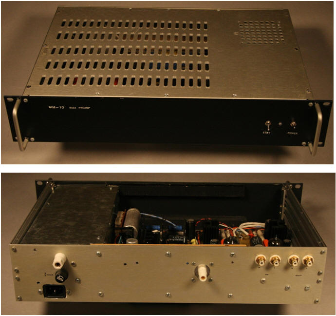
YFS MM-10a VACUUM TUBE PHONO PREAMP
The MM-10a phono preamp is our version of the simple twin triode passively equalized phono stage. There are so many commercially available variations of this topology (including kits) that coming up with a “new” design is almost impossible! It’s popularity attests to it’s soundness (no pun intended). The design objectives were:
-
Simple twin triode circuit using common tubes
-
Gain from 50-60dB for MC or MI cartridges
-
Passive equalization (include all poles)
-
Low noise, low output impedance regulated power supply
Since we are dealing with microvolt signals and equalization losses, very high gain is required to bring the phono output up to a reasonable level. Unfortunately, the circuit itself contributes noise that is amplified along with the musical signal. Minimizing circuit noise contribution requires high transconductance /low plate resistance tubes, which unfortunately generally have low Mu. Consequently, an additional gain stage or a step up transformer is required for low output cartridges. How can we get more gain and keep the transconductance up at the same time with out resorting to parallel tubes?

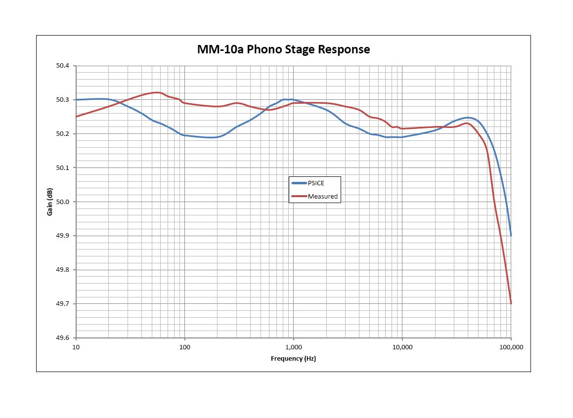
Some of the older Tektronix oscilloscopes used a low noise JFET input placed in series with the voltage gain transistor in a “totem pole” configuration. Replace the transistor with a triode and you have a high performance hybrid input stage. Note that the input is not a cascode since drain resistor R2 fixes the gain of the JFET, which then directly couples into the cathode of V1a. A voltage divider made up of R3 and R4 sets the JFET operating voltage. As it turns out, a 6DJ8/6922 combined with an SK170 (the classic low noise FET used for decades) provides a good balance between noise and gain. Nothing new here, many tube and solid-state circuits use the same technique (we happened to have hundreds of FET’s in stock!). Placing the RIAA equalization network after blocking capacitor C1 allows the use of low voltage precision capacitors for C2 and C3. Capacitor C1 now enters into the EQ design, so its value is also important. Capacitors C1 through C3 are metalized polypropylene selected to a 0.2% tolerance. Resistors R6 through R8 are metal film selected to 0.1% tolerance. The RIAA design included approximation of stray capacitance, inter-electrode capacitance, and stray inductance. Many people ague that splitting EQ between stages is better than a single network. Maybe, but we chose to isolate the EQ network from output loads. Adding an output buffer would allow splitting the EQ and isolating the network but would require another tube. We do indeed split the EQ and redistribute gain in our reference phono stage but is substantially more complex than this circuit. Output coupling capacitor C4 is metalized polypropylene and all other resistors are 1% metal film or wire wound. Keep in mind the schematic is a topological illustration only, supporting circuitry is not shown. Overall gain is about 56dB @ 1 kHz, which works well with our Dynavector high output moving coil cartridge. The gain was lowered to about 50dB for the Soundsmith VPI moving iron unit. THD is 0.03% @ 15mVp input. Theoretical and measured frequency responses are shown in the graph, not bad for such a simple circuit. Sonically it is very pleasing with virtually no fatigue after hours of listening, midrange presence is outstanding when used with the Dynavector or Soundsmith cartridges. It performs particularly well with classical music but has plenty of punch for rock and roll. We have found that a good power supply can make or break any audio circuit, perhaps that’s why this circuit seems to perform so well.
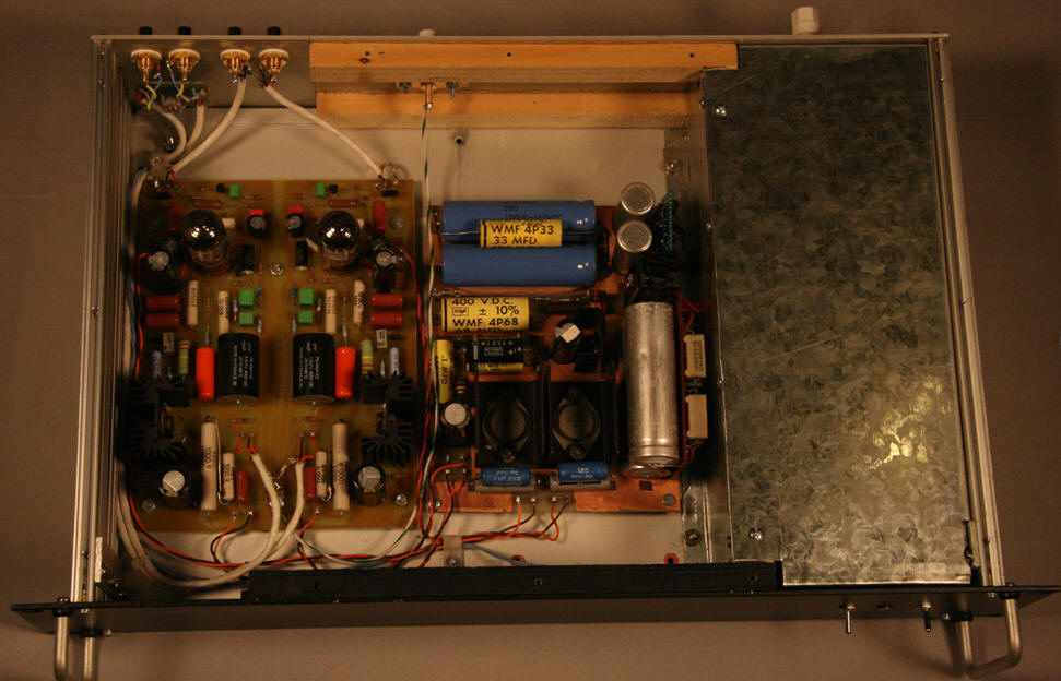
The power supply is our usual twin transformer arrangement with power and standby switches placed on the line side. Full magnetic shielding of the AC section and the delay circuit (which has its own power transformer) is incorporated. Filament and plate supply voltages are derived from standards silicon rectifiers with resistive and capacitive snubbers. Polycarbonate bypass capacitors are place across the electrolytic filter capacitors in both supplies. Sub-circuit PCB’s carry the rectifier and first stage filter capacitors to keep the main power supply board compact. Regulated +260V and +6V are supplied to the phono board. Each channel has a dedicated High voltage shunt regulator based on a high current low noise topology developed for driving high voltage bridge sensors in an aerospace application. Local shunt regulators have been used for decades in many transducer applications where PSRR is critical.

Recently I was informed that Vacuum State electronics has a similar design, as does Sonic Frontiers. Cool! That means I’m on the right track. Often circuit designers end up at the same point although they started with different objectives, apply different methodology, and have different knowledge bases. Most of my inspiration comes from classics texts, handbooks, and old transactions of the IRE from the 50’s and 60’s. Most of the “new” or even patented vacuum tube circuits can be found in the classic text “Vacuum Tube Amplifiers” by Valley & Wallman. I also adapt many of the techniques I have employed in instrumentation and low noise electronics design. We have also been chastised for ruining the tube sound with solid state devices in the signal path yet no one has been able detect the “contaminated” circuit in listening test. In fact, every subject preferred the JFET circuit to a similar pure tube topology (standard MM cartridge was used to allow gain matching between circuits).

That's it for now but stay tuned for more custom components from YFS!