YFS Products

by Kevin OBrien and Mike OBrien on 03/28/2011

YFS MODIFIED MCINTOSH MC75 MONOBLOCKS 

We had a chance here at YFS to modify a circa 1960's vintage set of McIntosh MC75 monoblocks. YES! These are truly classic amps that have that classic McIntosh sound that we tube-lovers really enjoy. When folks talk about a reference set of amps I believe these are it. Of course you can spend a lot more and find some really nice monoblocks out there but why would you?

OK, if you couldn't tell we are a bit biased towards McIntosh Labs but why wouldn't we be? Their gear sounds great!

So here's what we did to the MC75's that really got them sounding GREAT:

The original power supply in the MC75 in the 1960's was unique for its time in it's use of a voltage doubler. In stock form the power supply has been known to break into motor boating as the B+ filter capacitors deteriorate. On the other hand, many MC75's are still operating today with no issues. To maintain physical layout, we chose to reform the original electrolytic capacitors since the original units had relatively low leakage. The second step was to replace the entire power supply with modern design using Panasonic TSHC series electrolytics and ultra fast recovery rectifiers.  As it turned out, the sound was outstanding with the original components so we went no further.                                                                                                                                                                              

At YFS we understand that the MC75 is a pure classic but can be taken to the next level with modern components and matched vacuum tubes. Basic electronic components have come a long way in 40+ years so it makes sense that an inherently sound topology can be improved by simple component substitution.

No modifications were made to component values or the basic topology. We loaded the MC75 with matched Sylvania NOS 6550 output tubes and matched section (transconductance matched to 5%) NOS GE twin triodes (12AU7,12BH7, and12AZ7). We also added a power switch, replaced the stock power cord, increased bias supply capacitance, replaced all signal capacitors with modern polypropylenes, and substituted metal film resistors in critical places to reduce noise. We also replaced the speaker output terminal strips and the RCA input jack.

Needless to say, these amps are killer classics that sound amazing and look even cooler!

ENOUGH SAID!

 -KOB, MOB


by Mike OBrien on 03/07/2012


YFS CA-60a VACUUM TUBE PREAMPLIFIER


Modern music sources supply output voltages in the 1.0 to 2.0 volt range as opposed to phono cartridges where output levels are millivolts (0.001) or microvolts (0.000001). It makes sense to design a preamplifier optimized specifically for these modern sources. Our main listening room is equipped with such a unit employing an interesting WWII era topology. The inspiration came from the classic text from the MIT Radiation Lab Series, "Vacuum Tube Amplifiers" by G. Valley and H. Wallman. This monumental work was completed in 1948 (1st Edition) and resulted in 28 volumes, one of which was volume 18 mentioned above. Each time we thumb through it we seem to find something we missed or previously misinterpreted. Although complete functioning circuits (other than high gain RF amplifiers) aren’t shown, application examples and suggestions are scattered throughout the text. I believe it is currently available in hard copy (4th printing of 1st edition) and there are some of the original texts still available on Amazon and other websites. Chapters 10 and 11 covering frequency selective amplifier design and direct-coupled amplifier design illustrate applications of cathode coupled and differential input stages.

In the late 1980’s when The Library was tossing old magazines and journals we ran across a 1957 article in a volume of the IRE Transactions on Audio. The article was titled “Some Augmented Cathode Follower Circuits” by J. Ross MacDonald, who worked for Texas Instruments during WWII. The first paragraph and a few highlights read as follows:

The circuits, which are discussed in this paper, have very high input impedance, low output impedance, wide dynamic range, extremely low distortion, response from zero to the megacycles/second range, and input-output transfer ratios very close to or exceeding unity with no phase reversal.  They are suitable for many applications.  They may be used as grid drivers of high-power output tubes and will supply 100ma or more of positive grid current in such service.  They are suitable as isolation stages or buffers, particularly where their extremely high input impedance characteristics are desirable.  Their lack of phase reversal together with transfer ratios equal to or greater than unity and their vanishingly small distortion as well as wide dynamic range makes them particularly useful in active electronic filters and frequency selective amplifiers.

The circuits to be discussed occupy a somewhat intermediate position between ordinary cathode followers and operational amplifiers.

The circuit, shown in Fig 1, is more complex than an ordinary cathode follower, has an output resistance of 5.6 ohms, an input-output transfer ratio of 0.986, and can supply up to 200 ma of positive drive current without excessive distortion.

WOW!  Perfect. What more could you ask for (if it’s true) in a line amplifier requiring only 12 dB of gain? We proceeded to breadboard multiple versions of the circuits described in the paper.  We even added a few twists with MOSFET or JFET transistors where appropriate. The original CA-60 was all tube with 280V positive and negative rails. It sounded great but was impractical (at the time) to commercialize. Today it would not be an issue considering what the average audiophile preamplifier currently costs! Many incarnations including permutations and combinations of solid state current sources, MOSFET driven plates, MOSFET outputs, and regulated supplies were built and tested. 

One of the final CA-60a topologies is shown below. It employs a 12AX7 as the input tube (V1a&b) and one-half of a 12AU7 (V2a) as the output buffer. Using all 12AU7 tubes is also possible at the expense of overall gain. Both sounded good but slightly different, so the 12AX7 won out since we have a good stock of low noise matched section NOS units (these were from select stock for an analog computer). As usual, one objective was to use common, relatively inexpensive tubes. 

The input circuit looks like a standard differential input stage at first glance with C1 and R1 defining input impedance and low end roll-off. Plate voltages are matched by making R2=R3, however capacitor C2 bypasses the AC signal to ground forcing V1a to act as a cathode follower in AC terms. This feeds the second tube V1b via the cathode, leaving the grid as a feedback input. Several versions with separate regulators and driven plate via an integrator were tried but this simple arrangement was sonically equal. Output cathode follower V2a is DC coupled from the plate of V1b. Both the input and output stage have current sources made up of Q1-R4, and Q2-R5 to increase linearity. Diodes D1 and D2 along with bias resistor R6 form the voltage reference for the current sources. The feedback network composed of R7 and R8 defines the gain. Output capacitor C3 blocks DC from the cathode of V1b. It is possible to choose components to allow DC feedback directly from the cathode of V2a but that limits the choices of both open and closed loop gain. All capacitors are polypropylene or polystyrene while resistors in the amplifier circuit are either 1% metal film or 1% wire wound. Some carbon composition resistors were used in the power supply.

The power supply employs separate transformers for the filaments, B+, C-, and delay circuits. Individual high voltage regulators, negative regulators, and filament regulators are included. The delay operates an output shorting relay and controls the standby function. Transformers and AC portions of the supply are fully shielded.

The CA-60a physical layout is shown in the photos below. This version includes eight high level inputs, two for phono stages, and six for normal inputs. Output switching allows the output signal to be routed to A, B, or both A & B outputs. A direct output is included after the volume and balance controls allowing it to function as a passive “preamp” if desired. This arrangement is very convenient for comparing sources, new preamp circuits, and power amplifiers. Internal shielding of the input and power supply sections reduces noise and cross talk. All power and signal wire is PTFE insulated stranded silver plated copper.

Frequency and phase response from a PSPICE model is shown. The theoretical response shows a bandwidth from 0.10 Hz to 300 kHz with a phase shift of only +/- 2.0 degrees from 20 Hz to 20 kHz. Actual measured performance is 0.038% THD @ I kHz @ 2Vp input, 92dB SNR, and 260 ohms output impedance. We will re-measure and re-post measurements if there is any interest out there. (Ask us to and we will!)                                                                                                                      

Now the most obvious question: How does it sound? We have had many line stage preamps in our main set up. We quickly realized this topology was a top performer, equivalent to even the top commercial units. It is extremely detailed and open, but most notably it has a complete lack of “tube” or “solid state” character. It’s just plain neutral. The sound stage is solid with pinpoint imaging and very natural ambiance. Close attention to grounding, shielding, and power supply design keeps the noise floor extremely low. We have an upgraded version using shunt regulators but there is only a slightly detectable difference based on blind testing. Several custom versions have been built with no requests for upgrades. I believe Bruce Rozenblit (Transcendent Sound) offers a line stage called the Grid Preamp that has a similar topology but it lacks the symmetry we strove to preserve. My personal favorite is a design employing 6SL7 and 6SN7 tubes! This 6SL7/ 6SN7 breadboard is destined to replace our current CA-60a board. It's only a matter of time...


THANKS for tuning in and checking out our custom tube gear!

CLICK HERE TO CONTACT US IF YOU HAVE AN IDEA FOR A CUSTOM PRODUCT YOU WOULD LIKE US TO DESIGN/ BUILD FOR YOU!!!

- MOB


by Mike OBrien on 02/23/2012

YFS MM-10a VACUUM TUBE PHONO PREAMP

The MM-10a phono preamp is our version of the simple twin triode passively equalized phono stage. There are so many commercially available variations of this topology (including kits) that coming up with a “new” design is almost impossible! It’s popularity attests to it’s soundness (no pun intended). The design objectives were:

  1. Simple twin triode circuit using common tubes

  2. Gain from 50-60dB for MC or MI cartridges

  3. Passive equalization (include all poles)

  4. Low noise, low output impedance regulated power supply


Since we are dealing with microvolt signals and equalization losses, very high gain is required to bring the phono output up to a reasonable level. Unfortunately, the circuit itself contributes noise that is amplified along with the musical signal. Minimizing circuit noise contribution requires high transconductance /low plate resistance tubes, which unfortunately generally have low Mu. Consequently, an additional gain stage or a step up transformer is required for low output cartridges. How can we get more gain and keep the transconductance up at the same time with out resorting to parallel tubes?

Some of the older Tektronix oscilloscopes used a low noise JFET input placed in series with the voltage gain transistor in a “totem pole” configuration. Replace the transistor with a triode and you have a high performance hybrid input stage. Note that the input is not a cascode since drain resistor R2 fixes the gain of the JFET, which then directly couples into the cathode of V1a. A voltage divider made up of R3 and R4 sets the JFET operating voltage. As it turns out, a 6DJ8/6922 combined with an SK170 (the classic low noise FET used for decades) provides a good balance between noise and gain. Nothing new here, many tube and solid-state circuits use the same technique (we happened to have hundreds of FET’s in stock!). Placing the RIAA equalization network after blocking capacitor C1 allows the use of low voltage precision capacitors for C2 and C3. Capacitor C1 now enters into the EQ design, so its value is also important. Capacitors C1 through C3 are metalized polypropylene selected to a 0.2% tolerance. Resistors R6 through R8 are metal film selected to 0.1% tolerance. The RIAA design included approximation of stray capacitance, inter-electrode capacitance, and stray inductance. Many people ague that splitting EQ between stages is better than a single network. Maybe, but we chose to isolate the EQ network from output loads. Adding an output buffer would allow splitting the EQ and isolating the network but would require another tube. We do indeed split the EQ and redistribute gain in our reference phono stage but is substantially more complex than this circuit. Output coupling capacitor C4 is metalized polypropylene and all other resistors are 1% metal film or wire wound. Keep in mind the schematic is a topological illustration only, supporting circuitry is not shown. Overall gain is about 56dB @ 1 kHz, which works well with our Dynavector high output moving coil cartridge. The gain was lowered to about 50dB for the Soundsmith VPI moving iron unit. THD is 0.03% @ 15mVp input. Theoretical and measured frequency responses are shown in the graph, not bad for such a simple circuit. Sonically it is very pleasing with virtually no fatigue after hours of listening, midrange presence is outstanding when used with the Dynavector or Soundsmith cartridges. It performs particularly well with classical music but has plenty of punch for rock and roll. We have found that a good power supply can make or break any audio circuit, perhaps that’s why this circuit seems to perform so well.

The power supply is our usual twin transformer arrangement with power and standby switches placed on the line side. Full magnetic shielding of the AC section and the delay circuit (which has its own power transformer) is incorporated. Filament and plate supply voltages are derived from standards silicon rectifiers with resistive and capacitive snubbers. Polycarbonate bypass capacitors are place across the electrolytic filter capacitors in both supplies. Sub-circuit PCB’s carry the rectifier and first stage filter capacitors to keep the main power supply board compact. Regulated +260V and +6V are supplied to the phono board. Each channel has a dedicated High voltage shunt regulator based on a high current low noise topology developed for driving high voltage bridge sensors in an aerospace application. Local shunt regulators have been used for decades in many transducer applications where PSRR is critical.

Recently I was informed that Vacuum State electronics has a similar design, as does Sonic Frontiers. Cool! That means I’m on the right track. Often circuit designers end up at the same point although they started with different objectives, apply different methodology, and have different knowledge bases. Most of my inspiration comes from classics texts, handbooks, and old transactions of the IRE from the 50’s and 60’s. Most of the “new” or even patented vacuum tube circuits can be found in the classic text “Vacuum Tube Amplifiers” by Valley & Wallman. I also adapt many of the techniques I have employed in instrumentation and low noise electronics design. We have also been chastised for ruining the tube sound with solid state devices in the signal path yet no one has been able detect the “contaminated” circuit in listening test. In fact, every subject preferred the JFET circuit to a similar pure tube topology (standard MM cartridge was used to allow gain matching between circuits).

That's it for now but stay tuned for more custom components from YFS!

- MOB


by Mike OBrien on 02/22/2012

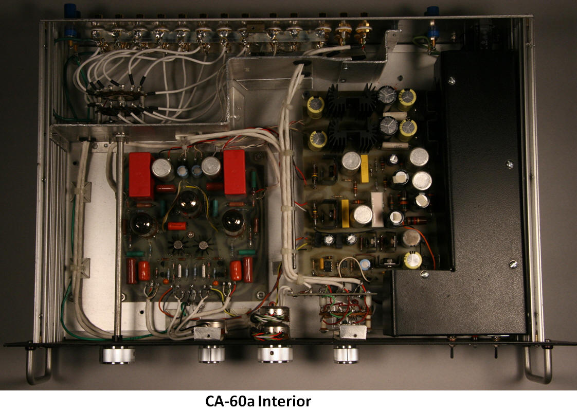
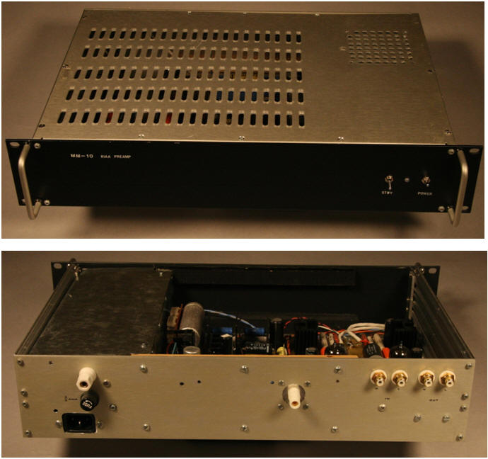
YFS CUSTOM CA-15a VACUUM TUBE PREAMPLIFIER

First, let’s keep in mind that this is not a dissertation on vacuum tube amplifier design, nor was this an attempt to produce a top notch audiophile preamp. We are describing the evolution of one of our custom preamps. If you are interested in circuit design there is a myriad of books and articles available (or drop us a line for specific questions).

Through the years five units with various chassis designs (customized inputs, outputs, and controls) were built, and several were upgraded. The CA-15 started in the late 80’s as a test bed for vacuum tube preamp designs. Our circuits were common topologies with obvious sonic limitations but the idea was to start with a “classic sound” and incrementally improve upon it. Simplicity was the key. What does a simple circuit sound like? We were pleasantly surprised, it wasn't world class but it was much more open and realistic than several respectable solid state preamps we tested. Through the years, pretty much at random, we tweaked the design to improve performance (usually as a break from other extended development projects).

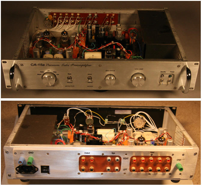
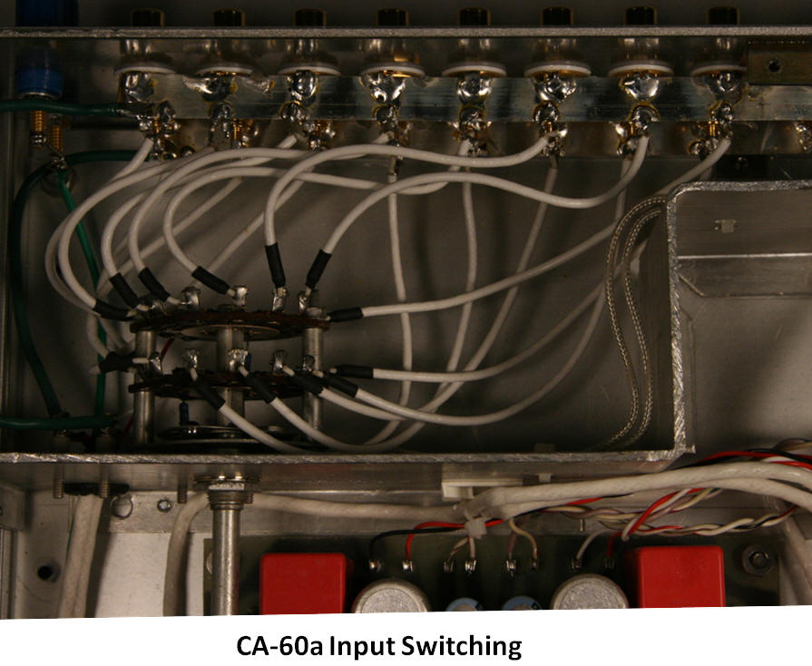
Each section of the preamp (power supply, high level, and phono) was an optimized version of a classic topology. A suite of switched inputs, direct output (after the volume/balance), high level output, a tape loop, and a mono switch were included. After many modifications, stints in dorm rooms and apartment moves, the unit is pretty beat up but is still working just fine. As a matter of fact, modified versions of the original PCB’s are still functioning in one of our first customer’s preamps! Remember that the objective was to see how a simple “classic” topology built with modern components would sound. It was used as a reference for evaluating upgrades and new topologies. As it stood, many jaws dropped when paired with solid state class A output power amps, especially with vinyl as the source. Compared to solid state and IC preamps of the time, the midrange detail and smoothness was startling. It did lack the bass punch and high end sparkle associated with top solid state and tube preamps of the time. To no one’s surprise it didn’t stand a candle to the old SP-11 (I’m convinced the 11 stood for number of tubes in the unit)! With limited bandwidth and a relatively soft power supply one can’t expect the world.

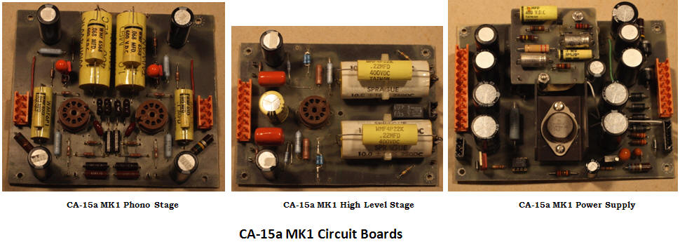
CA-15 Original Design

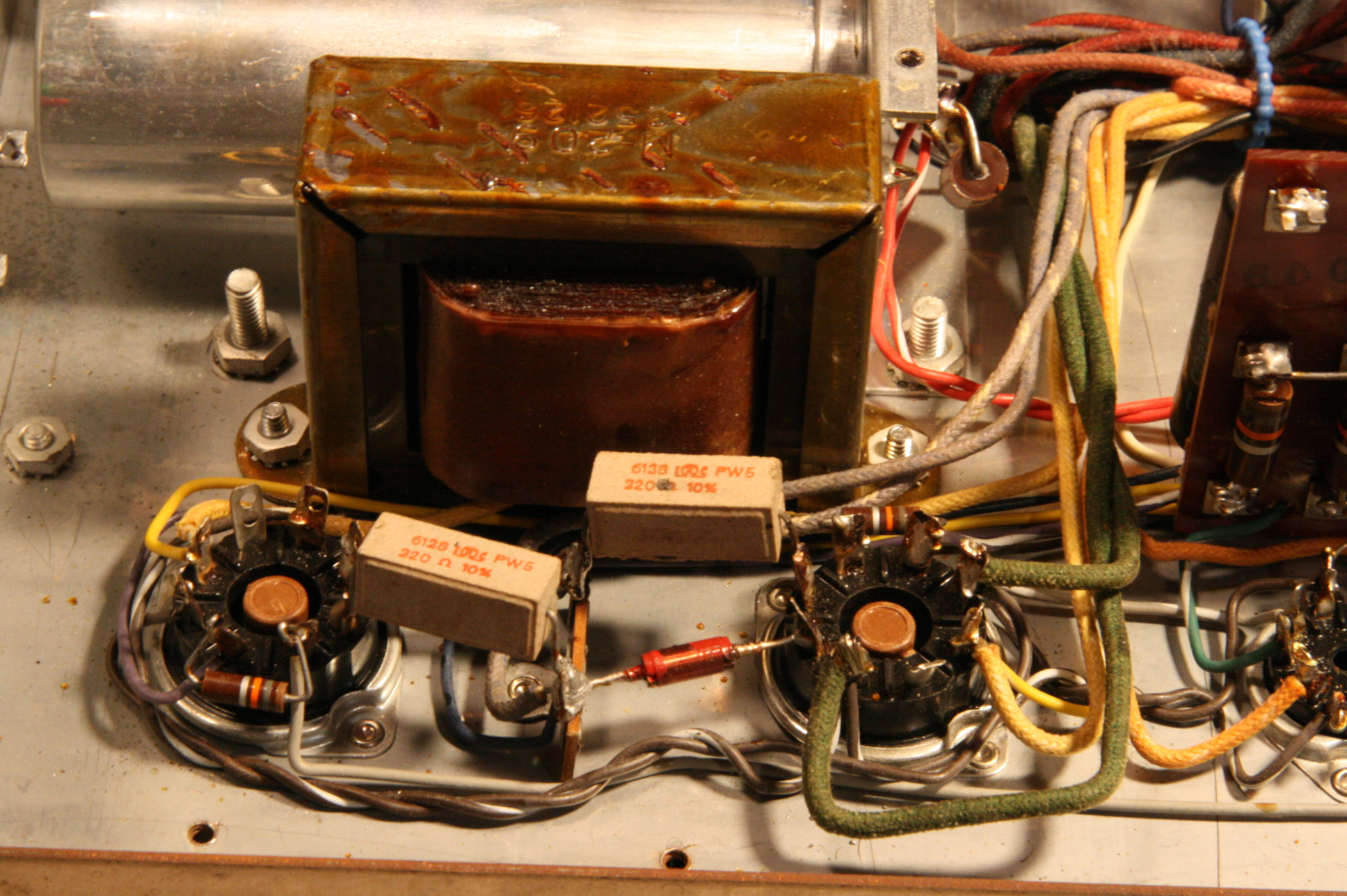
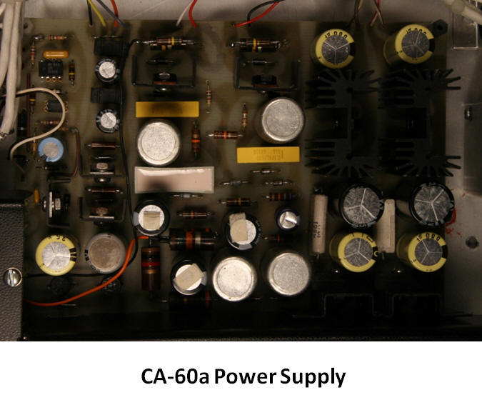
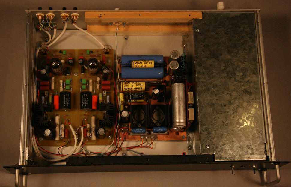
The power supply was a simple all solid state design using standard rectifiers and electrolytics with metalized polycarbonate film bypass capacitors in both the filament and high voltage supplies. Capacitance multipliers provided reasonable L and R channel isolation but there was no regulation per se. As in all our designs, separate filament and high voltage transformers were employed to eliminate any switches in the secondary circuits. The standby switch allowed tube filament to be warmed up before applying high voltage. A delay/standby circuit was also powered from the filament transformer. Although the version shown sports a magnetic/electrostatic shield over the power supply transformers and AC section, the original CA-15 was open with the transformers oriented for minimum hum.

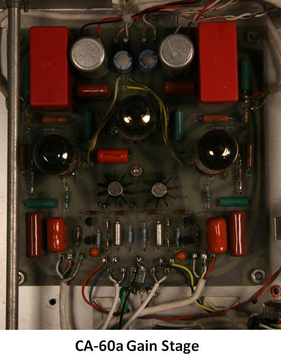
The high level circuit was a simple 12.5 dB gain Mu follower built around a 12AU7 with 100K input impedance and metalized polypropylene output blocking capacitors. Outputs were shorted by a timer operated relay allowing the high voltage to stabilize before connecting to the power amp (no pops due to DC offsets). Both carbon film and carbon composition resistors were used.

The phono stage was a classic 12AX7 two stage cascaded triode topology with bypassed cathode resistors to maximize stage gains. Active global feedback using a simple three element network eliminated issues with DC at the summing junction (cathode of first stage) but only approximated the ideal RIAA response. Feedback network components were 1% metal film resistors but the mica capacitors were only matched to 3%. Midband gain was 42 dB.

CA-15a and MK1 Versions

The next step was to update each sub circuit to more modern topologies, hence the “a”. The input switching made 1:1 comparisons simple. No modifications were made to the power supply for the first iteration, only high level amp and phono section were changed. The MK1 version had identical topology but included extra bypass caps, current source regulator zener string, and closer RIAA equalization network matching.                                                                                                     

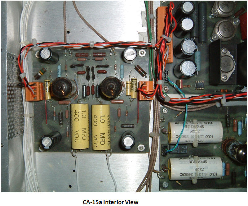
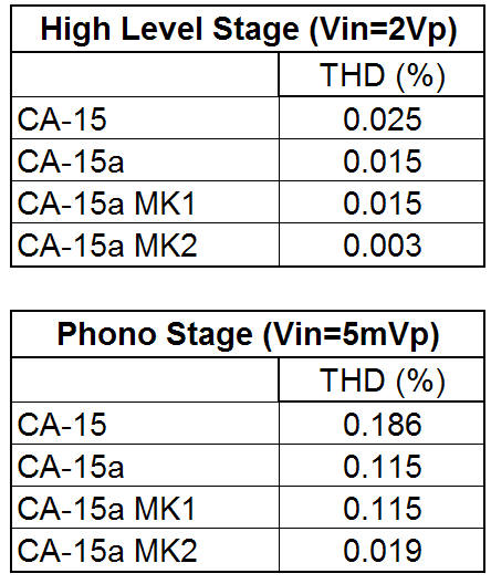
The high level section maintained the 12AU7 but employed a common cathode topology with unbypassed cathode resistors to control gain. Optimizing for minimum THD and dynamic range left us 14 dB of gain, a bit too much. The musical detail and bass response was noticeably better, probably due to the metal film resistors and extra high voltage filter capacitors. Unfortunately the stage had relatively high output impedance, not so good for driving long or high capacitance interconnects.

The phono stage retained the basic twin cascade topology but a small amount of positive feedback was achieved by resistively coupling the cathodes. This increased the open loop gain allowing a midband gain of 43 dB and response much closer to the ideal RIAA curve. Mica capacitors in the feedback network were matched to 1% which anchored the sound stage by reduced channel to channel “wandering”. High voltage filter capacitance on the PCB was also doubled.

Sonic improvement was immediately noticeable, especially in the midrange, but the bass was loose and the treble region was slightly muted. Everyone thinks I’m being over critical here, but after all, the whole idea was to make significant improvements over the reference topology. Overall, not bad and well worth the effort since it still outperformed the reference and several commercial preamps. One negative was the noise from the phono stage, a common problem when using low transconductance tubes in high gain circuits.

CA-15a MK2

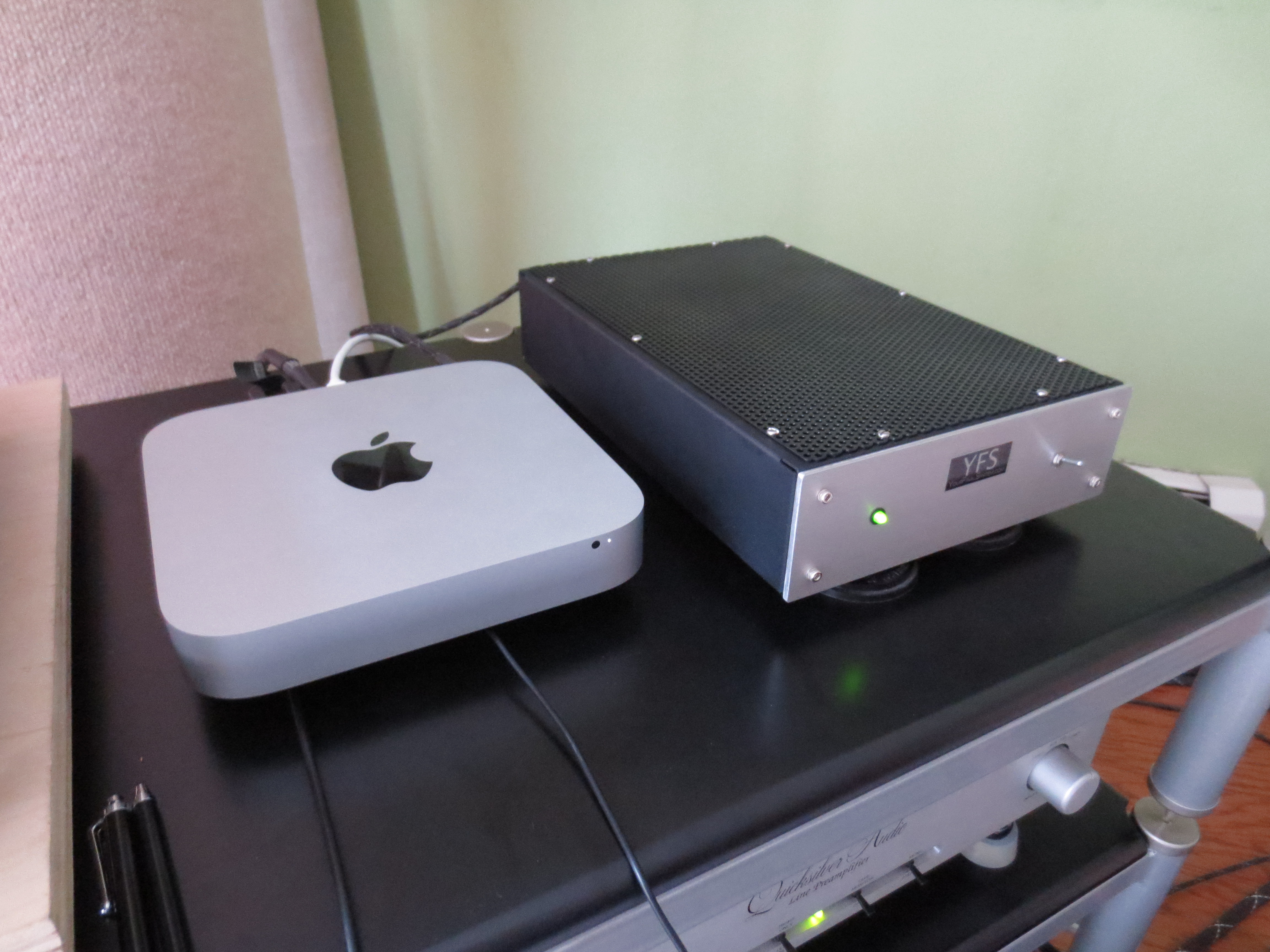
The objective of the final phase was to adjust gains to better suite modern sources, i.e. reduce high level stage gain and increase phono stage gain. I chose a hybrid topology where the tube contributed the majority of the gain and local feedback controlled overall stage gain. This is the current incarnation of the CA-15a being used in our lab/listening room.

A few simple modifications were made to the power supply which included converting the capacitance multipliers to buffered zener regulation, adding high voltage filter capacitance and polypropylene bypass capacitors, and increasing the high voltage transformer VA rating (doubled the core volume).

The hybrid high level stage retained the 12AU7 as the input but the plate is directly coupled to a P-channel MOSFET running at relatively high current. A series of resistors bias the output MOSFET, set second stage gain, and provide feedback to the cathode. Its low output impedance allowed the stage to drive long high capacitance interconnects without loss of highs. Total gain for the stage is only 9 dB, commensurate with the typical DAC level.

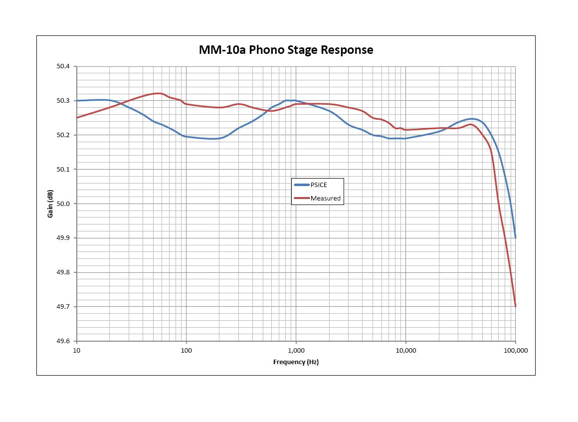
The passively equalized phono stage employs 0.5% matched metal film and polypropylene capacitors. It is implemented using two gain stages similar to the above topology. High input impedance and low output impedance are real advantages in this application. Lower resistor values for RIAA network (lower noise) can be selected without loading down the input stage or causing nonlinearity operation. Higher open loop gain allows accurate equalization over an extended frequency range (10Hz to 40kHz). Keeping the 12AX7 and directly coupling the plate to a MOSFET provides a midband gain of 50dB bringing the phono output to nearly the same level as a DAC through the high level stage.

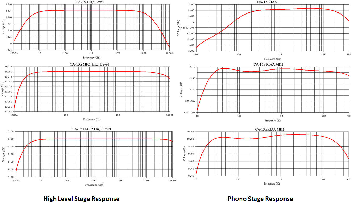
The more accurate RIAA equalization evens out the response and extends the bass and the treble regions, bass response is much tighter also. Overall sound was open and accurate but that “magic mid” was less apparent. Could a less accurate EQ sound better (it is a matter of taste)? This final design remained a reference preamp for many years. To make an “apples to apples” comparison we used PSPICE models to compute amplitude response of the high level and phono stages (phono is deviation from standard RIAA curve). This allowed us to eliminate effects of tube transconductance and component tolerance. Actual response for the CA-15a MK2 design are also shown. Interestingly enough, the old MK1 version is sonically equal or better than several currently available tube preamps.

We hope you enjoyed our break-down of our classic custom preamp.

-MOB


ADDENDUM ADDED on 02/26/2012:

There have been multiple questions regarding the topologies described in the article. Here are the basic schematics showing the functional components for each revision (no supporting circuitry).

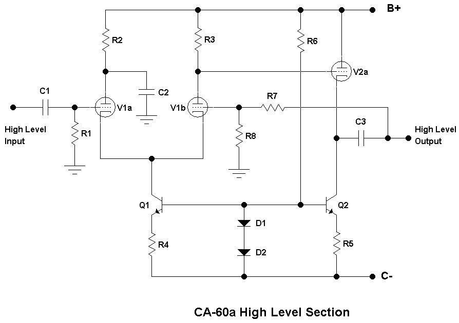
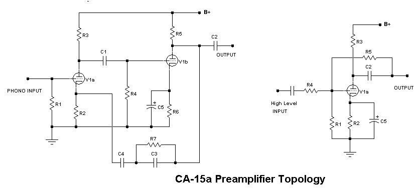
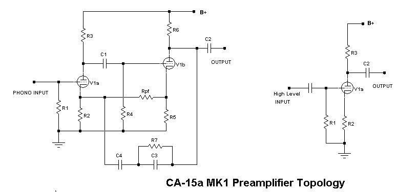
The CA-15a phono and high-level topological schematics are shown below. The original CA-15 is illustrated since the CA-15a is topologically identical, the differences being the power supply and the RIAA network values. The first stage of the phono circuit uses triode V1a in a standard common cathode arrangement with its gain defined by cathode resistor R2 and plate resistor R3. Blocking capacitor C1 and grid resistor R4 form the input circuit of V1b (also a common cathode arrangement). Notice the second stage has a bypass capacitor C5 across the cathode resistor R8 to maximize gain. The RIAA compensation is achieved by a feedback network made up of C3, C4, and R7, which returns to the cathode of V1a. Effects of output block capacitor C2 on the RIAA response is eliminated by placing it after the network. This is possible because C4 blocks DC from the plate of V1b. This was a popular circuit design for many old HiFi systems since it has minimum components count and was relatively simple to design. Most sonic differences stemmed from varying the gain ratios between stages and RIAA accuracy (although RIAA accuracy on many recordings is questionable to begin with). The high-level stage is an inverting Mu follower built around a single section of a dual triode. Gain is maximized by bypassing cathode resistor R2 with C5. Plate resistor R3 is optimized to provide maximum gain with the lowest possible output impedance since it must drive the feedback network and the load. Feedback network made up of R4 and R5 sets the gain and input impedance. Why didn’t we add a cathode follower at the output of each stage? Well, 95% of the DIY and commercial tube amps (DynacoMcIntoshMarantz, etc.) use that topology. We are experimenting with simplicity. The challenge is using only three dual triodes for an entire stereo preamp.

Looking at the MK1 schematic it is obvious that the phono sage is essentially the same as the CA-15a other than the addition of feedback resistor Rpf between cathodes. This arrangement provides a small amount of positive feedback, increasing open loop gain. This may very well be the reason for the openness and sweat midrange typical of this circuit. Optimization is a bit trickier since extra poles and zeros now show up in the transfer function. The more obvious change is in the high-level stage where the Mu follower is converted to a simple unbypassed common cathode with gain determined by R2, R3, and the mu of V1a. John Broskie has a variation that includes a cathode follower available as a kit. We have built many versions of this circuit and it does sound very natural! I highly recommend John’s Tube CAD Journal as a source of basic theory and some great new design ideas. I have only recently discovered the website, and I have to say, it is one of (perhaps “the”) best site on vacuum tube design I’ve seen. He also sells parts and kits for most of the circuits described in the articles making life easy for the DIY'er. I digress, back to the discussion at hand.

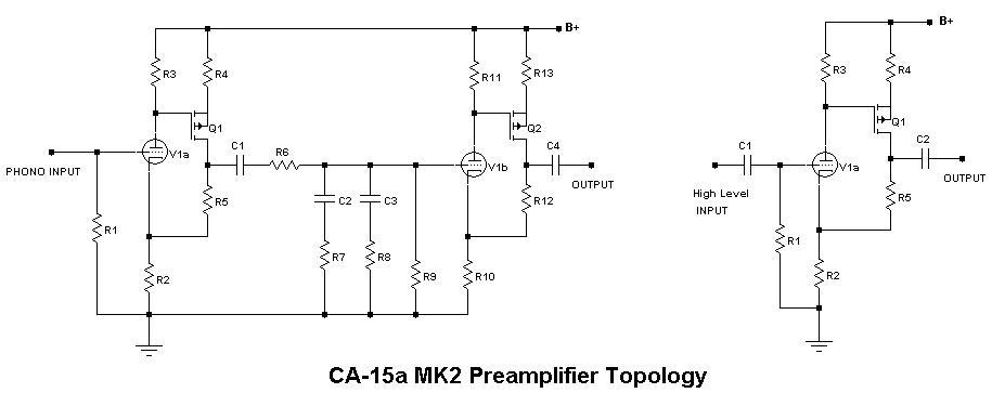
We cheated with the MK2 topology, still only three dual triodes, but we added a MOSFET for extra gain, and applied feedback. This circuit grew out of work done on interfacing custom feedback transducers. The original circuit used a JFET input device directly coupled to the MOSFET and a driven shield. Replacing the JFET with a vacuum tube was obvious. All stages are built around this basic configuration but actual component values vary from stage to stage. Design is a bit tricky since R2 and R5 provide global feedback, R5 and R4 set second stage gain, and R2 and R3 set first stage gain (a bit of interdependency, but nothing a good set of equations can’t solve). High voltage is also limited by the Vds of the P channel MOSFET which in turn limits gain available from the simple common cathode circuit. The phono stages run at relatively low current and high gain with a passive RIAA network (C2, C3, R6, R7, and R8) placed between stages. Blocking capacitor C1 allows us to use low voltage EQ capacitors, however the extra pole has to be included in the network design. Hope this answers some of your questions.


THANKS for reading! Until next time...

- MOB


by Brad Easton on February 2012

DIY SPEAKER "K08T21" FROM SOUND CLEARING HOUSE

Back in the summer of 2000 I watched a friend build the K08T21 step by step, start to finish not knowing a lot about building speakers.  The process was fun to see for the first time and painstakingly long during the box building stage.  I was there for the first listen and was present for the first 3 months breaking them in.  Even from the first listen before being broken in you could tell these speakers were on a different level from speakers sold at bigbox stores at that time.  My friend was using klipsch cornwalls before building these and never went back (they are now a fixture in the dining room scarcely used). 

It took me about a year before I decided to go ahead and build my own speakers. So I ordered them from Sound Clearing House (formerly speakerpage.com) back in the summer of 2001 just like my friend did.  I spent every night after work for 2 weeks making them downstairs in the basement workshop. Before you know it they're up and running,  sounding smooth and clear as can be.  

Rumor around the web was the SCH owner started working at Aperion Audio and was too busy to keep the site going.  Which was unfortunate, the owner was one of the nicest guys you'll ever talk to and he designed great sounding speakers. 

THE FOLLOWING WAS WRITTEN ON THE COVER LETTER THAT SCH SENT ME WITH THE INSTRUCTIONS ON HOW TO BUILD THE TOWER KIT:

"The K08T21 is a full range tower speaker.  It exemplifies the modern approach of getting higher performance through minimalist design - the concept being that sound waves should originate from as simple and coherent a source as possible.  This approach uses fewer drivers that are higher quality and engineered to work well together as a unit.

With this method, the woofer presents the greatest engineering challenge since it is asked to handle a very wide range of frequencies.  We originally designed the woofer entrusted with this assignment in a well-known studio monitor system.  A large motor, including a long-throw voice coil wound on a Kapton former, results in tight, well controlled bass reproduction capable of extending in to the deepest registers.  The mica-filled, polypropylene cone and well-matched butyl rubber suspension produce a radiating surface that is simultaneously high in stiffness and internal dampening; the reward is a detailed ("clear") yet exceptionally well-damped ("smooth") sound character extending well up into the midrange.

The K08T21's tweeter, made by the European manufacturer Vifa and found in speakers costing up to $25,000, uses a large, damped chamber behind the radiating surface, allowing it to operate down into the midrange.  In conjunction with the woofer's extended midrange performance it is possible for the entire audio bandwidth to be handled in a high performance manner by just two drivers, creating a speaker with only a single crossover point.  The result is a much simpler, more unified sound wave source than speaker systems using more drivers.

Tower designs like the K08T21 meet dual objectives of nice styling and good engineering.  Cosmetically, the appearance is sharp while the enclosure occupies a minimal amount of floor space.  From an engineer's point of view the tower design gets the sound-producing part of the speaker at the proper height without the use of speaker stands while the larger air volume makes for low bass potential.

The K08T21 is a fine example of simplifying design through good engineering and high quality components in the service of higher performance."

 END OF COVER LETTER.

I also ordered the DIY Speaker kit "K10S10" from Sound Clearing House to fill in the low frequencies. I currently use the speaker connections and do not use the RCA inputs as you can see in the picture below.  The x-over frequency is set as low as it can go at 40 Hz. This setup allows for seamless bass response between the sub drivers and the tower drivers.  I know what your saying....this isn't a true 2 channel system.  But you wouldn't know I'm using a subwoofer if you were listening to it blind.  I've heard this is the most accurate way to reproduce bass with 2 channel audio. Without the K10S10 subwoofer the K08T21's will lack the bass response to reproduce the low frequency thud you expect.

THE FOLLOWING WAS WRITTEN ON THE COVER LETTER THAT SCH SENT ME WITH THE INSTRUCTIONS ON HOW TO BUILD THE SUB KIT:

Subwoofers are required to play a Jeckel and Hyde role. In their home theater life, they shake the walls with frightfully loud, low, monstrous bass of special effects. Yet, during subtle music passages, they are asked to vanish, rendering, say, a cello so convincingly that you can believe your speakers have disappeared.

As Dr. Jeckel, the K10S10's 120 watt amplifier and mass loaded, progressive suspension, 10" woofer allows it to be a brute while as Mr. Hyde, it's well damped moving system and electronically equalize output results in tight, well controlled, natural sounding bass.

Several features permit it to fit into any system. Of course it has adjustable volume and crossover frequency control, allowing it to interface with any speaker system it's asked to work with, and high and low level stereo inputs allowing it to work with any set of electronics. And of course, it has auto on/off so that it will "standby" when it's not in use. But it also has two other less common features that are important.

  1. 24dB/octave rolloff slopes (rather than the more common 12dB/octave) insuring that midrange frequencies don't "leak through" to the subwoofer. These higher frequencies betray the subwoofer as a the source of bass information, destroying the illusion that the bass originates from your other speakers.
  2. Phase reversing switch, allowing you to get the subwoofer's output in phase with the main speakers regardless of the subwoofer's location

It all adds up to a strong performer that shines in any role its asked to play, from brutish special effects to the subtle nuances of music, with any supporting cast of electronics and staged in any living room.

 END OF COVER LETTER.

My 2 channel system has come a long way since 2000 with the addition of various DAC's. Not only do these speakers keep impressing me with the newer upgrades to my source components but....these speakers are still being used in some of YFS's listening rooms to this day and are comparable to many Rocky Mountain Audio Fest setups I've heard. Thank you to Sound Clearing House for making available a truly "high end" speaker that is still standing the test of time now that we're entering the realm of true HD audio. If you were one of the lucky ones that grabbed a Sound Clearing House DIY kit, I'm sure you know what I'm talking aboutAnd Remember...Just because it's a DIY speaker, doesn't mean it doesn't sound really great.

-BJE

Associated Equipment for this Review:

  • YFS CPU Prototype - HD Ref 1
  • YFS Custom Room Treatment
  • Musical Fidelity V-DAC
  • YFS Custom Direct Preamp and Custom 6L6 Tube Power Amp
  • YFS Custom Interconnects, Cables, and USB Cables


by Kevin OBrien on October 15, 2021

YFS 2020 M1 MAC MINI MODIFICATION

When will we see an update to the latest 2018 Mac Mini? We have been patiently waiting for Apple to release another model since the 2018 variant. Why have we been waiting so patiently? The 2018 version of Apple's Mini demands the largest power draw of any Mini made to date. That means we would need to totally revamp our YFS PS-12m linear power supply to output even more power, mainly in the current delivery department. This was something we really didn't want to take on as we've already squeezed every last drop of power from our original design. We were dreading having to start from scratch with a new LPS as we just do not have the time.

So, we were stuck, until now... Apple has recently unveiled their M1 chip in the latest Mac Mini form factor for 2020! This is exciting stuff. The 2020 M1 version of the Mac Mini requires the least amount of power of any Mini produced thus far. By placing most of the critical components on the motherboard itself, including RAM and the super efficient M1 processor, the 2020 Mac Mini uses minimal power and draws very little current. Apple placed the same switching power supply inside the M1 Mini as the 2018 Mini, but the extra power is not needed (The 2018 Mini stock switching power supply is rated at ~150 Watts!).

This is the perfect scenario to allow our current YFS PS-12m linear power supply to be integrated into the latest Mini form factor. We came up with an entirely re-designed YFS internal power filter just for this purpose.

So what do we mean when we say "modify" exactly? The modification consists of three steps. First, we take apart the Mini and remove the stock Apple switching power supply. Second, we place our YFS M1 Internal Power Filter in its place (pictured below) and put the Mini back together. Third, we simply hook the PS-12m umbilical up to the rear of the Mini. DONE! Now you're off to the races. 

There's a considerable difference in sound quality between the Late 2012 Mini of old and this latest 2020 M1 version. You don't have to strain to hear it either. It's obvious. Our soundstage grew wider, taller, and deeper. Small nuances in the music suddenly appeared and called attention to themselves like never before. There appeared to be a sense of air and space that was missing previously. This was all brought to our attention while streaming lossy Pandora from our web browser! Just wait until we put on some local Hi-Res files.

We did just that after our initial Pandora session. We fired up some SRV Texas Flood in DSD128 using Audirvana 3.5. WOW!  (Here is a link to the AV 3.5 download as AV Studio is the latest version). We recently found ourselves on a SACD-ripping kick with our Sony BDP-S5100. This has opened up an entirely new world as far as available DSD to feed our DACs. Anyway, back on track. Let's try some Dire Straits. Next we listened to our Brothers In Arms MOFI SACD rip and came away with a similar conclusion as above. WOW!

We are confident in our assessment here.  The new YFS M1 Mini is our favorite digital source for the money!  There's simply just not that much $$$ going into this transport and what we're getting out of it is incredible. A 2020 M1 Mini can be had for ~ $1000. Our YFS modification will run you $700. Most of our Mac Mini customers already have our YFS PS-12m linear power supply in their racks. If not, there are plenty of options out there if our PS-12m price tag is too high ($1800 MSRP). Luckily, there are plenty of manufacturers making 'affordable' 12V power supplies these days.

Finally, great sounding digital can be had for minimal expense, all things considered. Not only that, you can still control your own digital destiny. We don't like 'streamers' as there's no way to fix them when they go wonky or need to be updated. With a Mac Mini, you have a way to update, add music easily, and repair without being out of commission for very long (almost all of us have an Apple repair center close by). OS X software updates and music playback software updates become elementary and the user is in control. This allows us to pivot and change when new software is released (and new hardware for that matter as DACs change quickly). We like this... We like this A LOT.  Apparently, so do our customers as this modification is our best selling product!

If you've been waiting to get into that latest digital source component and you have a 12 Volt power supply laying around (that can deliver at least 4.5 Amps), why not give it a shot? Feel free to drop us a line and we can help with any questions you may have.

* The YFS M1 Internal Power Filter is available on its own. Send us $375 if you want to do the modification at home *

THE YFS MAC MINI IS BACK!

Thanks for reading.

- YFS Design Team


by Kevin OBrien on August 30th, 2012

VSA SHOWROOM: HD REF-3 SE INSTALL!

We'd like to tell our readers about a recent trip we took to the Von Schweikert Audio factory in Southern California. We were lucky enough to have some of the greatest guys in the audiophile industry (Albert and Damon Von Schweikert) allow us to take a factory tour in their beautiful new facility in Riverside, CA. Our goal was to demo our HD Ref-3 SE for Albert and Damon as well as the head of Acquisitions for the VSA team. As it turns out, the trip morphed into much more than that. What a fun and exciting experience for us!

We'd like to show some pics of the gear we were allowed to demo our Ref-3 with. The list below sums up the equipment that we integrated our HD Ref-3 SE with:

DAC:  Audio Research DAC8 ($4,995 MSRP)

Preamp:  Coincident Statement Line Stage ($5,000 MSRP)

Amplification:  Jolida Music Envoy Monoblocks ($8,750 MSRP)

Speakers:  VSA VR-35 Export Deluxe ($7,995 MSRP)

Cables:  VSA Master-Built speaker cables and interconnects

Our first impression of the VR-35's was WOW! We then hooked up our Ref-3 and our jaws dropped. HOLY TOLEDO! I think we may have surprised ourselves when we reached the conclusion that this is the best we've ever heard our Ref-3 perform. We tried several DAC's including the Jolida Glass FX Tube DAC, the Lindemann USB-DAC 24/192, and finally the Audio Research DAC8. They all sounded REALLY good but the surprise for us was the Jolida Glass FX. It really did sound good and it was the cheapest out of the three. Nice work Jolida. The Lindemann USB-DAC 24/192 sounded great but we felt it favored the high end of the frequency response and was a little too forward in its presentation. Overall, it sounded great but it didn't seem to fit in with the rest of the demo system like the Jolida did. Lastly, the Audio Research DAC8, which was the clear winner, sounded wonderful. It gave us all the detail of the Lindemann with the perfect laid back sound of the tubed Jolida Glass FX. What else can we say, the DAC8 impressed us to say the very least!

Now on to the point of the trip, the HD Ref-3. Several of Albert's and Damon's favorite discs (Redbook) were ripped and a plethora of Hi-Res FLAC's were played to evaluate the Ref-3. After many hours of listening and tweaking, we at YFS felt the Ref-3 was a great addition to the VSA listening room. Apparently so did Albert and Damon. They decided to keep the Ref-3 and they weren't going to look back! n as well as the head of VSA Acquisitions for allowing us to take time out of their day to show them our latest computer music server. It means a lot to us and we feel very grateful to be a part of such a special group. And by the way Damon, lunch was awesome!  THANKS VSA!

-KOB


by Kevin OBrien on August 8, 2013

YFS PS-12m MAC MINI POWER SUPPLY/ MODIFICATION               
                                                                                                                         

Since we already make custom linear DC power supplies, we figured we'd try our luck at a Mac Mini linear power supply. We feel the other Mini power supplies on the market are not quite up to par. When we find a PS that is up to the task, the price is daunting! So, let's try and change all that with our YFS PS-12m.

We have been busy designing and building our prototype PS-12m and I think we really nailed it. We offer a 12V/ 7.5Amp DC linear power supply with an 18" umbilical which attaches to the rear of the Mac Mini via a 2.5mm DC barrel jack. We remove the internal switching power supply and replace it with high quality silver leads straight from the Mini motherboard fed into a high quality internal power filter, then to a 2.5mm x 5.5mm DC power jack on the Mini rear panel. We can make the umbilical connector anywhere from 12" to 36". We've tested both extremes and found no difference in performance. Please specify umbilical length when ordering the YFS PS-12m.

We offer a stand-alone Mac Mini modification which involves adding an SSD for your OS (supplied by you or us)/ extra RAM (supplied by you or us), adding the silver leads to the circuit board and jack, adding an internal power filter, as well as adding the 2.5mm DC barrel jack. We can do the Mini mod for our customers and they can use our competition's power supply if they wish.

Our customers can also buy a DIY kit for their Mini if they choose. This allows foreign customers and/ or folks who have a good handle on soldering/ electronics work to save some cash. We are not responsible for broken Mini's after installing our YFS Mini Mod Kit. Modify at your own risk. We think this is a nice option. We can also do the Mini Mod and provide our linear DC power supply as a package and give our customers a break on the Modification/ PS combo pricing. It's totally up to you. You can buy them separately or as a pair. Versatility is key. 

Potential customers may ask what differentiates our PS from the other guys? Well, we actually supply more current than the stock Mini switching PS which is rated at 7.1 Amps. Looking at our competitors, we don't see how it's even remotely possible to supply anywhere close to 7 Amps without heat sinks or a perforated top cover. Why do we need a perforated cover or heat sinks? We have to get rid of the heat generated by the 7.5 Amps. There's just no way to break the laws of physics. Next time you look at a linear Mini PS, look at it closely and ask yourself which method the designer is using to dump heat. If you don't see any way to efficiently transfer the heat, then the PS is most likely putting out closer to 3 to 4 Amps, not 7.5.             

The main question you may have is, "How does it sound?" Well, we get better bass response, more detail, better slam, a wider and taller sound stage, and more dynamics.

Our power supplies are built from scratch, by hand, in Upstate NY and carry a 1 year warranty. We don't source our products from distant off-shore locations and then assemble them in the USA. We're not saying there's anything wrong with that but we feel our customers deserve much better quality than that. Again, our products are entirely hand crafted in the USA. We stand behind our products and each and every PS-12m is made to order. You may ask yourself, "Is it worth the wait?" We think so. Please allow 6 to 8 weeks for completion and two weeks for delivery. We know it's a long wait, but it may not take that long depending on our current work load.

Contact us for pricing, availability, and lead times.

THANKS for reading!

-YFS Design Team


by Brad Easton and Kevin OBrien on 06/24/2012

YFS HD.Ref-3 MUSIC SERVER TRANSPORT

We wanted to let our readers in on some major work we've undertaken lately. We love our HD Ref-2 music server transport but we knew we wanted to beef up our processing power while maintaining near silent operation. We figured there had to be a way to get our Ref-2 practically silent. It's been a long road but we've made it, finally.

The older Ref-2 designs were based on 6-core processing, a 1 TB disc drive, 16 GB of RAM, a Blu-Ray ROM, and a basic DVI/ HDMI/ D-SUB PCI video card.  We housed the Ref-2 in an industrial, rack-mountable, lockable steel chassis. We added the SOtM USB PCI card option for the Special Edition and the SSD models.

The NEW Ref-3 model employs 6-core processing, a  512 GB SSD drive, 32 GB of RAM,  the same video card, the same chassis as the Ref-2, the SOtM USB PCI card, and an external power supply for the SOtM card. We also offer a RAID option that can bring the SSD storage up to 1 TB if desired. The major benefit of the Ref-3 over our previous models is the nearly inaudible operation as well as more RAM, more SSD storage, and an external power supply for the SOtM USB card.

We decided to come up with two models for the Ref-3 and discontinue our Ref-2. We now offer a YFS HD Ref-3 Base Model and a YFS HD Ref-3 Special Edition. The 'Base Model' and the 'Special Edition' are exactly the same server but the 'Base Model' is missing the SOtM USB PCI card as well as the external power supply for the SOtM USB card. It also only employs 16 GB of RAM instead of 32 GB. The 'Special Edition' contains the SOtM USB PCI Card as well as the power supply to go with it. Both units offer the same 512 GB SSD storage drive. Remember, our servers are completely custom so you can get as much SSD storage as you want. We'll charge you accordingly for the extra storage space.

Our server is the only currently available dedicated music server transport on the market that packs all of the above options in a semi-affordable package. We haven't been able to find an external power supply option for the SOtM card let alone a server that could easily integrate one so we decided to do it ourselves and push the computer audio envelope. Just plug our non-switching power supply into the rear of the unit in order to separately power the SOtM USB card. You don't have to take the cover off to unplug the power supply when you want to move both units. VERY HANDY. We have accomplished all of this at under $13,000. Simply AMAZING!!!

We do use fans in our latest design because with all the processing power we provide, there's no way to cool our servers without them. Don't worry, they're not audible during normal operation. Don't get caught up in the mini-ATX motherboard craze to get a fan-less server. If that's your goal, just buy a high-end SSD laptop and you'll get better performance than the competition's currently available music servers.

The other guys claim their designs are "silent" and "fan-less". You CAN achieve one without the other. We don't think many folks realize this. Our competitors' "silent" designs are not truly silent. Why don't these server manufacturers tell you what SPL their products are running at? Because if they did, you'd realize they're not really silent at all. We aren't afraid to test our operating SPL's. In fact, you can see into our design with the cover on as we have implemented an open top and we're not hiding anything from anybody. We don't have to.

We implement Windows 7 Professional for an operating system along with Foobar 2000, JRiver Media Center, or Album Player for a digital playback suite. We prefer Album Player based on its playback abilities. The Ref-3 is fully compatible with the latest standard-res and hi-res file formats (16, 24, and 32  bit word lengths and 44.1/ 48/ 88.2/ 176.4/ 192/ 352.8/ 384 kHz sampling rates). The Ref-3 also plays DSD64 and DSD128 files! (with compatible playback software)

Our control options for the Ref-3 are the same as the Ref-2. The Ref-1 needed a keyboard, monitor, and mouse to operate. The Ref-3 is fully operational with ONLY A TABLET/ LAPTOP/ PHONE! The user doesn't need to plug anything in to the Ref-3 to get it up and running and fully operational except an ethernet cable. Choose your favorite tablet/ laptop, power on the Ref-3, wait 45 seconds, and then start controlling your new Ref-3 server anywhere your local network allows. VERY COOL!

We think you'll enjoy using the most powerful, user friendly music server the audiophile world has to offer. It's only a matter of time until the other guys are scrambling to catch up. 

Contact us with questions.  We're here to help!

Remember, the Ref-3 is totally custom designed to your specs. If you want some features taken away or added, it's your call!  We can make it exactly the way you want it. No problem! We offer a full in-home install for an additional fee. Contact us for details. The entire install is done in under 2 hours. This service is only available in the contiguous United States. We can provide install support over the phone/ e-mail for any other location. Our products are available in 110V-120V as well as 220V-240V. Just let us know where you need your YFS server to operate and we'll take care of it!

We can now ship a fully functional Ref-3 via UPS to the lower 48 (contiguous United States)!!!

We offer package deals on our YFS USB cables if you plan on buying a server too.

Contact us for more details.

THANKS for your interest in YFS products!

- YFS Design Team


Subcategories

YFS Cables & Interconnects

YFS Power Amps

YFS Pre Amps

YFS Speakers

YFS Music Servers

YFS Power Supplies

Connect with us today!